On the other hand, the classes within the src package are not intended to be directly used by the virtual-lab developers. The documentation of this package describes the implementation details required to modify and extend the VirtualLabBuilder library.
In fact, the classes within ViewElements and VLabModels packages
inherit from classes defined within src package, inheriting the structure
and the behavior, and adding only the documentation oriented to the virtual-lab
developer.
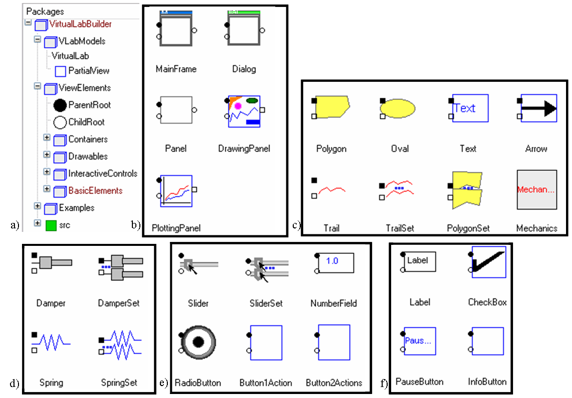
Figure 1.VirtualLabBuilder library: a) general structure; and
classes within the following packages: b) Containers; c) Drawables; d) Mechanics;
e) InteractiveControls; and f) BasicElements..
Steps to describe a virtual-lab
The virtual-lab definition includes the description of the introduction, the model, the view, and the bidirectional flow of information between the model and the view. The virtual-lab definition process is outlined next.
- Virtual-lab model. Any Modelica model can be transformed into other Modelica model suitable for interactive simulation. Essentially, the proposed methodology consists in modifying the model so that all the variables that need to be changed interactively during the simulation (i.e., the interactive variables) are formulated as state variables. In particular, parameters are redefined as time-dependent variables whose time-derivative is equal to zero. Input variables are reformulated analogously in order to become interactive variables. Modelica's when clause and reinit operator allow describing instantaneous changes in the value of the state variables. This feature is exploited in order to perform the instantaneous changes in the value of the interactive variables produced by the user's interaction. Some of these model manipulations could be performed automatically by a software tool. However, at the present time, they have to be carried out manually by the virtual-lab developer.
- Virtual-lab view. The virtual-lab developer has to define a Modelica class describing the virtual-lab view. This class has to extend another class, named PartialView, that is included in VirtualLabBuilder library (see Figure 1a). The communication interval (i.e., time interval between to consecutive model-view communications) is a parameter of the PartialView class (Tcom), that can be set by the virtual-lab developer. PartialView class contains a pre-defined component: the root element for the view description. The classes describing the graphic components are within the Containers, Drawables, InteractiveControls and BasicElements packages of VirtualLabBuilder library (see Figures 1b, 1c, 1e and 1f respectively. The virtual-lab designer has to compose the virtual-lab view class by instantiating and connecting the required graphic components. The graphic components have to be connected forming a structure, whose root is the root element. The connections among the graphic components determines their layout in the virtual-lab view.
- Virtual-lab set up. The virtual-lab developer has to define a Modelica
class describing the complete virtual-lab. This class has to contain an
instance of the VirtualLab class, which is within the VirtualLabBuilder
library (see Figure 1a). VirtualLab class has the following parameters:
- Model-to-view communication interval (Tcom).
- Name of the java file (the content of this file is generated during the model initialization process).
- Class describing the virtual-lab model.
- Class describing the virtual-lab view.
- Virtual-lab translation and execution. The virtual-lab developer needs to translate using Dymola an instance of the Modelica class defined in Step 4 into an executable file (i.e., dymosim.exe file). The virtual-lab is started by executing this file.
- Automatic code generation and run. At the beginning of the simulation run, some calculations are performed in order to solve the model at the initial time. The initial sections of the Modelica model describing the virtual-lab are evaluated. In particular, the initial sections of the interactive graphic objects composing the virtual-lab view class and of the PartialView class are executed. These initial sections contain calls to Modelica functions, which encapsulate calls to external C-functions. These C-functions are Java-code generators. As a result, during the model initialization, the Java code of the virtual-lab view is automatically generated, compiled, packed into a jar file and executed. Also, the communication procedure between the model and the view is automatically set up. This communication is based on a client-server architecture: the C-program generated by Dymola (i.e., dymosim.exe, see Step 5) is the server and the Java program (which has been automatically generated during the model initialization) is the client. Once the jar file is executed, the initial layout of the virtual-lab view is displayed and the client-server communication is established. Then, the model simulation starts. During the simulation run, there is a bi-directional flow of information between the model and the view. The model sends the data required to refresh the view and the view sends the value of the variables modified due to a user action at the time instant when the communication is performed. The time interval between two consecutive model-view communications was defined in Step ef{enum:overview2}.
Package Content
| Name | Description |
|---|---|
| Classes to describe the virtual-lab view and to set-up the virtual-lab | |
| Package including interactive graphic elements | |
| Some examples of use | |
| Source code |
HTML-documentation generated by Dymola Tue Jul 24 18:58:08 2007.