A set of physical magnitudes is grouped
into the same causal connector if their connection corresponds to the same
model application context.
Four different model application contexts have been distinguished in JARA:
The causal connectors defined in JARA have
only one allowed computational causality.
This is not imposed by the design
methodology, but it is a result of the JARA modeling approximations.
Attending to their computational causality,
two types of JARA causal connectors are distinguished: capacitive and resistive.
Definition 1. A connector is capacitive if and only if it satisfies the following two conditions:
Definition 2. A connector is resistive if and only if it satisfies the following two conditions:
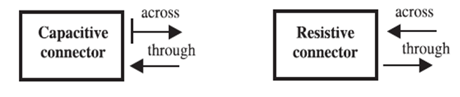
The capacitive and resistive connectors are causal connectors. The computational causalities of the capacitive and resistive connectors have been schematically represented in Figure 1. The arrow pointing toward the element represents a computational input and the arrow pointing outwards means computational output. The vertical line perpendicular to the arrow represents the breaking of the causality computational loop by means of integrators (the bond graphs notation is adopted ).
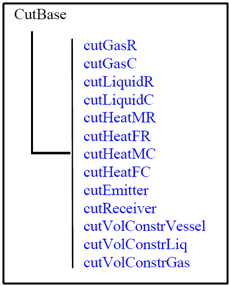
The mass-flow, heat-flow, information transmision and volume constraint causal connector classes are described in Table 1, 2, 3 and 4, respectively.
The following notation
has been used. Suffix C: capacitive connectors; suffix R: resistive connectors; (I):
computational inputs; and (O): computational outputs.
Two types of mass-flow connectors have been defined in JARA: one for liquid
mixtures and the other for gaseous ones. A capacitive and a resistive connector class
have been defined for each type.
Two types of heat-flow connectors have been defined in JARA, one for heat
conduction, heat flow-M, and the other for heat convection, heat flow-F. A
capacitive and a resistive connector class have been defined of each type.
The necessity of describing the information transmission arises when modeling
automatic control loops. This is the purpose of the JARA's information transmission
connectors. Two types of information transmission connectors are defined in JARA:
emitter and receiver (see Table 3). Both types of causal connectors are only composed
of across variables, whose number and meaning depends on the application.
The fourth type of connector in JARA, the volume constraint connector (see
Table 4), models the constraints that the recipients impose on the CVs volume.
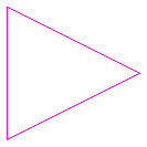
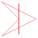
Causal connectors icons allow identifying easily the type of causal connector. The icon color represents the type of flow: liquid, gas or information. Capacitive connectors icons are filled and resistive connectors icons are bordered. The ''pointed'' shape denotes the existence of through variables (gas, liquid and heat flow connectors). The way of orienting the connector in the interface (inward or outward direction) depicts the sign criteria of the connector through variables.
Table 1. Mass-flow connectors.|
Causal connector |
Across variables |
Flow variables |
|
Gas flow-R |
Moles number (vector) Temperature (I) Pressure |
Molar-flow (vector) Energy flow (O) |
|
Gas flow-C |
Moles number (vector) Temperature (O) Pressure |
Molar-flow (vector) Energy flow (I) |
|
Liquid flow-R |
Mass (vector) Temperature (I) Pressure |
Molar-flow (vector) Energy flow (O) |
|
Liquid flow-C |
Mass (vector) Temperature (O) Pressure |
Molar-flow (vector) Energy flow (I) |
|
Causal connector |
Across variables |
Flow variables |
|
Heat flow-M-R |
Matter (vector) Temperature (I) |
Heat flow (O) |
|
Heat flow-M-C |
Matter (vector) Temperature (O) |
Heat flow (I) |
|
Heat flow-F-R |
Matter flow (vector) Temperature (I) |
Heat flow (O) |
|
Heat flow-F-C |
Matter flow (vector) Temperature (O) |
Heat flow (I) |
|
Causal connector |
Across variables |
Flow variables |
|
Info. emitter-C |
Signal (vector) (O) |
|
|
Info. receiver-R |
Signal (vector) (I) |
|
|
Causal connector |
Across variables |
Flow variables |
|
Volume constraint |
Three variables |
One variable |
| Name | Description |
|---|---|
| Information emitter. | |
| Gas flow - Connector Capacitive. | |
| Gas flow - Connector Resistive. | |
| Heat flow - Connector F-C. Connector for the heat convection. | |
| Heat flow - Connector F-R. Connector for the heat convection. | |
| Heat flow - Connector M-C. Connector for the heat conduction. | |
| Heat flow - Connector M-R. Connector for the heat conduction. | |
| Liquid flow - Connector C. Connector for the liquid flow. | |
| Liquid flow - Connector R. Connector for the liquid flow. | |
| Information receiver. | |
| Volume constraint - Gas. | |
| Volume constraint - Liquid. | |
| Volume constraint - Vessel. |
 JARA2i.cutsB.cutEmitter

| Type | Name | Default | Description |
|---|---|---|---|
| Integer | dim | Dimension of the Signals vector |
| Type | Name | Description |
|---|---|---|
| Integer | dim | Dimension of the Signals vector |
| Real | signal[dim] | Signals |
connector cutEmitter " Information emitter."

   parameter Integer dim "Dimension of the Signals vector";

   Real signal[     dim] "Signals";

end cutEmitter;
 JARA2i.cutsB.cutGasC

| Type | Name | Default | Description |
|---|---|---|---|
| Integer | nComp | 1 | Number of components |
| Type | Name | Description |
|---|---|---|
| Integer | nComp | Number of components |
| Real | molG[nComp] | Mol number of each component [mol] |
| Real | tempG | Temperature of the gas mixture [T] |
| Real | pressG | Gas pressure [M.L-1.t-2] |
| flow Real | molGF[nComp] | Molar flow of each component [mol.t-1] |
| flow Real | energyGF | Energy flow [M.L2.t3] |
connector cutGasC "Gas flow - Connector Capacitive."

   parameter Integer nComp = 1 "Number of components";

   Real molG[ nComp](  unit="mol") "Mol number of each component";
   Real tempG(         unit="T") "Temperature of the gas mixture";
   Real pressG(        unit="M.L-1.t-2") "Gas pressure";

   flow Real molGF[ nComp](        unit="mol.t-1")
    "Molar flow of each component";
   flow Real energyGF(             unit="M.L2.t3") "Energy flow";


end cutGasC;
 JARA2i.cutsB.cutGasR
| Type | Name | Default | Description |
|---|---|---|---|
| Integer | nComp | 1 | Number of components |
| Type | Name | Description |
|---|---|---|
| Integer | nComp | Number of components |
| Real | molG[nComp] | Mol number of each component [mol] |
| Real | tempG | Temperature of the gas mixture [T] |
| Real | pressG | Gas pressure [M.L-1.t-2] |
| flow Real | molGF[nComp] | Molar flow of each component [mol.t-1] |
| flow Real | energyGF | Energy flow [M.L2.t3] |
connector cutGasR "Gas flow - Connector Resistive."

   parameter Integer nComp = 1 "Number of components";

   Real molG[ nComp](  unit="mol") "Mol number of each component";
   Real tempG(         unit="T") "Temperature of the gas mixture";
   Real pressG(        unit="M.L-1.t-2") "Gas pressure";

   flow Real molGF[ nComp](        unit="mol.t-1")
    "Molar flow of each component";
   flow Real energyGF(             unit="M.L2.t3") "Energy flow";


end cutGasR;
 JARA2i.cutsB.cutHeatFC

| Type | Name | Default | Description |
|---|---|---|---|
| Integer | nComp | 1 | Number of components |
| Type | Name | Description |
|---|---|---|
| Integer | nComp | Number of components |
| Real | matterF[nComp] | Matter amount of each component [M or mol] |
| Real | tempF | Temperature [T] |
| flow Real | heatF | Heat flow [M.L2.t-3] |
connector cutHeatFC
  "Heat flow - Connector F-C. Connector for the heat convection."

   parameter Integer nComp= 1 "Number of components";

   Real matterF[ nComp](        unit="M or mol")
    "Matter amount of each component";
   Real tempF(                  unit="T") "Temperature";

   flow Real heatF(             unit="M.L2.t-3") "Heat flow";


end cutHeatFC;
 JARA2i.cutsB.cutHeatFR
| Type | Name | Default | Description |
|---|---|---|---|
| Integer | nComp | Number of components |
| Type | Name | Description |
|---|---|---|
| Integer | nComp | Number of components |
| Real | matterF[nComp] | Matter amount of each component [M or mol] |
| Real | tempF | Temperature [T] |
| flow Real | heatF | Heat flow [M.L2.t-3] |
connector cutHeatFR "Heat flow - Connector F-R.
 Connector for the heat convection."

   parameter Integer nComp "Number of components";

   Real matterF[ nComp](        unit="M or mol")
    "Matter amount of each component";
   Real tempF(                  unit="T") "Temperature";

   flow Real heatF(             unit="M.L2.t-3") "Heat flow";


end cutHeatFR;
 JARA2i.cutsB.cutHeatMC

| Type | Name | Default | Description |
|---|---|---|---|
| Integer | nComp | Number of components |
| Type | Name | Description |
|---|---|---|
| Integer | nComp | Number of components |
| Real | matter[nComp] | Matter amount of each component [M or mol] |
| Real | temp | Temperature [T] |
| flow Real | heatF | Heat flow [M.L2.t-3] |
connector cutHeatMC " Heat flow - Connector M-C.
 Connector for the heat conduction."

   parameter Integer nComp "Number of components";

   Real matter[ nComp](        unit="M or mol")
    "Matter amount of each component";
   Real temp(                  unit="T") "Temperature";

   flow Real heatF(            unit="M.L2.t-3") "Heat flow";


end cutHeatMC;
 JARA2i.cutsB.cutHeatMR
| Type | Name | Default | Description |
|---|---|---|---|
| Integer | nComp | Number of components |
| Type | Name | Description |
|---|---|---|
| Integer | nComp | Number of components |
| Real | matter[nComp] | Matter amount of each component [M or mol] |
| Real | temp | Temperature [T] |
| flow Real | heatF | Heat flow [M.L2.t-3] |
connector cutHeatMR " Heat flow - Connector M-R.
 Connector for the heat conduction."

   parameter Integer nComp "Number of components";

   Real matter[ nComp](        unit="M or mol")
    "Matter amount of each component";
   Real temp(                  unit="T") "Temperature";

   flow Real heatF(            unit="M.L2.t-3") "Heat flow";


end cutHeatMR;
 JARA2i.cutsB.cutLiquidC

| Type | Name | Default | Description |
|---|---|---|---|
| Integer | nComp | Number of components |
| Type | Name | Description |
|---|---|---|
| Integer | nComp | Number of components |
| Real | massL[nComp] | Mass of each component [M] |
| Real | tempL | Temperature [T] |
| Real | pressL | Pressure [M.L-1.t-2] |
| flow Real | massLF[nComp] | Mass flow of each component [M.t-1] |
| flow Real | energyLF | Energy flow [M.L2.t-3] |
connector cutLiquidC " Liquid flow - Connector C.
 Connector for the liquid flow."

   parameter Integer nComp "Number of components";

   Real massL[ nComp](  unit="M") "Mass of each component";
   Real tempL(          unit="T") "Temperature";
   Real pressL(         unit="M.L-1.t-2") "Pressure";

   flow Real massLF[ nComp](           unit="M.t-1")
    "Mass flow of each component";
   flow Real energyLF(                 unit="M.L2.t-3") "Energy flow";


end cutLiquidC;
 JARA2i.cutsB.cutLiquidR
| Type | Name | Default | Description |
|---|---|---|---|
| Integer | nComp | Number of components |
| Type | Name | Description |
|---|---|---|
| Integer | nComp | Number of components |
| Real | massL[nComp] | Mass of each component [M] |
| Real | tempL | Temperature [T] |
| Real | pressL | Pressure [M.L-1.t-2] |
| flow Real | massLF[nComp] | Mass flow of each component [M.t-1] |
| flow Real | energyLF | Energy flow [M.L2.t-3] |
connector cutLiquidR " Liquid flow - Connector R.
 Connector for the liquid flow."

   parameter Integer nComp "Number of components";

   Real massL[ nComp](  unit="M") "Mass of each component";
   Real tempL(          unit="T") "Temperature";
   Real pressL(         unit="M.L-1.t-2") "Pressure";

   flow Real massLF[ nComp](             unit="M.t-1")
    "Mass flow of each component";
   flow Real energyLF(                   unit="M.L2.t-3") "Energy flow";


end cutLiquidR;
 JARA2i.cutsB.cutReceiver
| Type | Name | Default | Description |
|---|---|---|---|
| Integer | dim | Dimension of the Signals vector |
| Type | Name | Description |
|---|---|---|
| Integer | dim | Dimension of the Signals vector |
| Real | signal[dim] | Signals |
connector cutReceiver " Information receiver."

   parameter Integer dim "Dimension of the Signals vector";

   Real signal[     dim] "Signals";

end cutReceiver;
 JARA2i.cutsB.cutVolConstrGas

| Type | Name | Description |
|---|---|---|
| Real | vcE[3] | Recipient Volume |
| flow Real | vcF | Gas Volume |
connector cutVolConstrGas "Volume constraint - Gas."

   Real vcE[3] "Recipient Volume";
   flow Real vcF "Gas Volume";

   // Real      dummyVol  (unit="L3")              "Dummy variable";
   // Real      dummyVol1 (unit="L3")              "Dummy variable";   //= dummyVol
   // Real      press     (unit="M.L-1.t-2")       "Pressure";

   // flow Real vesselV   (unit="L3")              "Vessel volume";


end cutVolConstrGas;
 JARA2i.cutsB.cutVolConstrLiq

| Type | Name | Description |
|---|---|---|
| Real | vcE[3] | Recipient Volume |
| flow Real | vcF | Liquid Volume |
connector cutVolConstrLiq "Volume constraint - Liquid."

   Real vcE[3] "Recipient Volume";
   flow Real vcF "Liquid Volume";

   // Real  vesselV       (unit="L3")              "Vessel volume";
   // Real  dummyVol      (unit="L3")              "Dummy variable";
   // Real  pressTopRef   (unit="M.L-1.t-2")       "Pressure";

   // flow  Real  fluidV  (unit="L3")              "Fluid volume";


end cutVolConstrLiq;
 JARA2i.cutsB.cutVolConstrVessel

| Type | Name | Description |
|---|---|---|
| Real | vcE[3] | Recipient Volume |
| flow Real | vcF |
connector cutVolConstrVessel "Volume constraint - Vessel."

   Real vcE[3] "Recipient Volume";
   flow Real vcF;

   // Real   vesselV    (unit="L3")          "Vessel volume";
   // Real   dummyVol   (unit="L3")          "Dummy variable";
   // Real   dummyPress (unit="M.L-1.t-2")   "Pressure";
   // flow Real dummyVolF  (unit="L3")       "Dummy variable";  // = -dummyVol


end cutVolConstrVessel;