Drawables package includes the container elements and the base classes that the library developer has to extend to create new container elements.
The relationship between the interfaces, the base classes and the classes describing the drawables elements is shown in Figure 1. The class names are placed inside rectangles. The partial class names are placed inside rectangles with dashed line borders. An arrow going from a rectangle A, containing one class, to a rectangle B, indicates that the classes contained in rectangle B inherit from the class contained in rectangle A.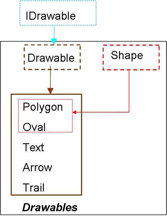
| Name | Description |
|---|---|
| Base class of the classes describing drawable elements | |
| Shape | Base class of the classes lasses describing 2-D drawables with shape |
| Polygon | |
| Oval | |
| Displays a string | |
| Draws an arrow | |
| Draws a trail | |
| Draws a set of trails | |
| Draws a set of polygons | |
| Mechanic elements |
 VirtualLabBuilder.src.ViewElements.Drawables.Drawable

Drawable class has to be inhereted from the classes describing drawable elements. This class inherits from the IDrawable class.
The Drawable class includes the code required to perform the two following tasks:
| Type | Name | Description |
|---|---|---|
| Parent | pLeft | Connector of drawable components |
| Child | cLeft | Connector of drawable components |
partial model Drawable
  "Base class of the classes describing drawable elements"
 extends Interfaces.IDrawable;
  import Modelica.Utilities.*;

//Global Variables*****************
  outer Boolean refreshView "true if the view is refreshed";
  outer Integer p "Socket Descriptor";

protected
  Boolean windowClosed( start = false, fixed = true);
  outer parameter String fileName "Name of the java file";
  outer parameter String fComponent;
//********************************
  Real out1( start = 1);
  parameter Integer numInt=1;
  parameter Integer numIntColor=1;
  Real colors[numIntColor+1];
  Real vert[ numInt+1];

algorithm
    when (change(refreshView) and
                                 not (windowClosed)) then
        out1 :=if ((numInt + numIntColor) > 0) then CServer.sendOutput(
      p,
      numInt,
      vert[1:numInt],
      numIntColor,
      colors[1:numIntColor],
      num) else 1;
    end when;

  when (out1 <0.5) then
      Modelica.Utilities.Files.removeFile(fComponent);
      CServer.shutdownConnection(p);
      windowClosed :=true;
      terminate("Main window closed");

 end when;

end Drawable;
Shape class is inhereted from classes describing 2-D drawables with shape (i.e., Polygon and Oval). This class includes the parameters required to describe the color properties of the drawable element.
This class includes the declaration of the two following variables: lineColor[:] and fillColor[:]. The value of lineColor[:]/fillColor[:] is set to the value of the lineColorp[:]/fillColorp[:] parameters if the intlineColor/intfillColor parameter is 0, or it has to be provided by the virtual-lab developer otherwise.
| Type | Name | Default | Description |
|---|---|---|---|
| booleanValue | filled | "true" | True if the poligon is filled and false otherwise |
| Color | lineColorp[4] | {0,0,0,255} | The color used for the lines of the component |
| Color | fillColorp[4] | {0,0,255,255} | The color used to fill the component |
| Integer | intLineColor | 0 | 1 if the line color change in time and 0 otherwise |
| Integer | intFillColor | 0 | 1 if the filling color change in time and 0 otherwise |
partial model Shape
  "Base class of the classes lasses describing 2-D drawables with shape "
  parameter TypesDef.booleanValue filled = "true"
    "True if the poligon is filled and false otherwise";
  parameter TypesDef.Color lineColorp = {0,0,0,255}
    "The color used for the lines of the component";
  parameter TypesDef.Color fillColorp = {0,0,255,255}
    "The color used to fill the component";

  parameter Integer intLineColor = 0
    "1 if the line color change in time and 0 otherwise";
  parameter Integer intFillColor = 0
    "1 if the filling color change in time and 0 otherwise";
  Real lineColor[4];
  Real fillColor[4];

equation
  if (intLineColor== 0) then
   lineColor = lineColorp;
  end if;
  if (intFillColor == 0) then
   fillColor = fillColorp;
  end if;


end Shape;
 VirtualLabBuilder.src.ViewElements.Drawables.Polygon
This class extends the following two classes: Drawable and Shape.
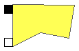
Draws a polygonal curve specified by the coordinates of its vertexes points.
The x and y coordinates of the vertexes points of the polygon (x[:] and y[:] vectors) can be linked to model variables.
| Type | Name | Default | Description |
|---|---|---|---|
| booleanValue | filled | "true" | True if the poligon is filled and false otherwise |
| Color | lineColorp[4] | {0,0,0,255} | The color used for the lines of the component |
| Color | fillColorp[4] | {0,0,255,255} | The color used to fill the component |
| Integer | intLineColor | 0 | 1 if the line color change in time and 0 otherwise |
| Integer | intFillColor | 0 | 1 if the filling color change in time and 0 otherwise |
| Integer | nPoints | 1 | Number of vertices |
| booleanValue | closed | "true" | True if the poligon is closed and false otherwise |
| Integer | intVertexesX[:] | zeros(nPoints) | intVertexesX[i] = 1 if coordinate x of vertex i changes in time |
| Integer | intVertexesY[:] | zeros(nPoints) | intVertexesY[i] = 1 if coordinate y of vertex i changes in time |
| Real | stroke | 1.0 | Stroke used to draw the lines |
| Integer | gradient | 0 | 1 if there is a gradient in the filling color |
| Real | p1[2] | {0,0} | Position where the color gradient starts |
| Color | color1[4] | {192,192,192,255} | Color at point p1 |
| Real | p2[2] | {0,10} | Position where the color gradient finishes |
| Color | color2[4] | {64,64,64,255} | Color at point p2 |
| booleanValue | cyclic | "true" | True if the color gradient is cyclic |
| Type | Name | Description |
|---|---|---|
| Parent | pLeft | Connector of drawable components |
| Child | cLeft | Connector of drawable components |
model Polygon "Polygon"
              extends Drawable(numIntColor =  (intLineColor+intFillColor)*4, numInt = numIntX+numIntY);
              extends Shape;
  import Modelica.Utilities.*;
  parameter Integer nPoints = 1 "Number of vertices";
  parameter TypesDef.booleanValue closed = "true"
    "True if the poligon is closed and false otherwise";
  parameter Integer intVertexesX[:] = zeros(nPoints)
    "intVertexesX[i] = 1 if coordinate x of vertex i changes in time";
  parameter Integer intVertexesY[:] = zeros(nPoints)
    "intVertexesY[i] = 1 if coordinate y of vertex i changes in time";
  parameter Real stroke = 1.0 "Stroke used to draw the lines";

  input Real x[nPoints] "X coordinates of the polygon vertices";
  input Real y[nPoints] "y coordinates of the polygon vertices";
  parameter Integer gradient = 0
    "1 if there is a gradient in the filling color";
  parameter Real p1[2] = {0,0} "Position where  the color gradient starts";
  parameter TypesDef.Color color1 = {192, 192, 192, 255} "Color at point p1";
  parameter Real p2[2] = {0, 10} "Position where the color gradient finishes";
  parameter TypesDef.Color color2 = {64, 64, 64, 255} "Color at point p2";
  parameter TypesDef.booleanValue cyclic= "true"
    "True if the color gradient is cyclic";
protected
  parameter Integer numIntX = Functions.Sum(intVertexesX);
  parameter Integer numIntY = Functions.Sum(intVertexesY);

  Integer j;
  Integer i;

initial algorithm

  num :=Functions.processingFile(fComponent);
  Functions.fPolygon(fileName, "node"+String(pLeft.nodeReference), "node"+String(num), String(num), x, y, nPoints, filled, integer(lineColor),
  integer(fillColor), closed, intVertexesX, intVertexesY, intLineColor, intFillColor, stroke, gradient, p1, color1, p2, color2, cyclic);

algorithm
  j :=1;
  i :=1;

 vert[numInt+1] := -1;
 colors[numIntColor+1] :=-1;
  while j<=nPoints and (numIntX>0) and (i<=numIntX) loop
     vert[i] :=x[j];
     i  :=if (intVertexesX[j] < 1) and (i<=numIntX) then i else i + 1;
     j :=j + 1;
  end while;
 j:=1;
  while j<=nPoints and (numIntY>0) and (i<=numInt) loop
     vert[i]:=y[j];
     i  :=if intVertexesY[j] < 1 then i else i + 1;
     j :=j + 1;
  end while;
  i :=1;
  while  (intLineColor)>0 and (i<=numIntColor) loop
     colors[i] := lineColor[i];
     i := i+1;
  end while;
    j :=i;
    i :=1;
  while i<= numIntColor and (intFillColor)>0 loop
    colors[j] :=fillColor[i];
    j := j + 1;
    i :=i + 1;
  end while;
equation

end Polygon;
 VirtualLabBuilder.src.ViewElements.Drawables.Oval
This class extends the following two classes: Drawable and Shape.
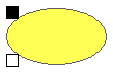
Oval class draws an oval. The position of the oval center (Center[:]/i> variable) and the lengths of the axes (Axes[:] variable) can be linked to the model variables.
Parameters
| Type | Name | Default | Description |
|---|---|---|---|
| booleanValue | filled | "true" | True if the poligon is filled and false otherwise |
| Color | lineColorp[4] | {0,0,0,255} | The color used for the lines of the component |
| Color | fillColorp[4] | {0,0,255,255} | The color used to fill the component |
| Integer | intLineColor | 0 | 1 if the line color change in time and 0 otherwise |
| Integer | intFillColor | 0 | 1 if the filling color change in time and 0 otherwise |
| Integer | intCenter | 0 | intCenter = 1 ==> the center changes in time |
| Integer | intAxes | 0 | intAxes = 1 ==> the axes change in time |
| Real | stroke | 1.0 | Stroke used to draw the lines |
| Integer | gradient | 0 | 1 if there is a gradient in the filling color |
| Real | p1[2] | {0,0} | Position where the color gradient starts |
| Color | color1[4] | {192,192,192,255} | Color at point p1 |
| Real | p2[2] | {0,10} | Position where the color gradient finishes |
| Color | color2[4] | {64,64,64,255} | Color at point p2 |
| booleanValue | cyclic | "true" | True if the color gradient is cyclic |
| Type | Name | Description |
|---|---|---|
| Parent | pLeft | Connector of drawable components |
| Child | cLeft | Connector of drawable components |
model Oval "Oval"
  extends Drawable(numIntColor = (intLineColor+intFillColor)*4, numInt = (intCenter+intAxes)*2);
  extends Shape;
  import Modelica.Utilities.*;

  parameter Integer intCenter = 0
    "intCenter = 1 ==> the center changes in time";
  parameter Integer intAxes = 0 "intAxes = 1 ==> the axes change in time ";

  input Real Center[2] "x coordinates of the poligon vertexes";
  input Real Axes[2] "y coordinates of the poligon vertexes";
  parameter Real stroke = 1.0 "Stroke used to draw the lines";
  parameter Integer gradient = 0
    "1 if there is a gradient in the filling color";
  parameter Real p1[2] = {0,0} "Position where  the color gradient starts";
  parameter TypesDef.Color color1 = {192, 192, 192, 255} "Color at point p1";
  parameter Real p2[2] = {0, 10} "Position where the color gradient finishes";
  parameter TypesDef.Color color2 = {64, 64, 64, 255} "Color at point p2";
  parameter TypesDef.booleanValue cyclic= "true"
    "True if the color gradient is cyclic";
protected
  Integer j;
  Integer i;

initial algorithm
 num :=Functions.processingFile(fComponent);
  Functions.fOval(fileName, "node"+String(pLeft.nodeReference), "node"+String(num), String(num), Center, Axes, filled, integer(lineColor),
 integer(fillColor), intCenter, intAxes, intLineColor, intFillColor, stroke, gradient, p1, color1, p2, color2, cyclic);

algorithm
  j :=1;
  i :=1;
  vert[numInt+1] :=-1;
  colors[numIntColor+1] :=-1;
 if (intCenter>0 and intAxes>0) then
   for i in 1:2 loop
     vert[i] :=Center[i];
     vert[i+2] :=Axes[i];
   end for;
 end if;
 if (intCenter>0 and intAxes==0) then
  for i in 1:2 loop
     vert[i] :=Center[i];
   end for;
 end if;

 if (intCenter==0 and intAxes>0) then
  for i in 1:2 loop
     vert[i] := Axes[i];
   end for;
 end if;
  i :=1;
  while  (intLineColor)>0 and (i<=numIntColor) loop
     colors[i] := lineColor[i];
     i := i+1;
  end while;
    j :=i;
    i :=1;
  while i<= numIntColor and (intFillColor)>0 loop
    colors[j] :=fillColor[i];
    j := j + 1;
    i :=i + 1;
  end while;
equation

end Oval;
 VirtualLabBuilder.src.ViewElements.Drawables.Text

This class inherits from the Drawable class.
Text class displays a string. The position of the string
center (Center[:] variable) can be linked to the model variables.
| Type | Name | Default | Description |
|---|---|---|---|
| Color | textColor[4] | {0,0,0,255} | string color |
| Integer | intCenter | 0 | = 0 if the center change in time and 0 otherwise |
| String | textString | "" | String displayed by the element |
| Type | Name | Description |
|---|---|---|
| Parent | pLeft | Connector of drawable components |
| Child | cLeft | Connector of drawable components |
model Text "Displays a string"
            extends Drawable(numIntColor = 0, numInt = intCenter*2);

  import Modelica.Utilities.*;

  parameter TypesDef.Color textColor = {0,0,0,255} "string color";

  parameter Integer intCenter = 0
    "= 0 if the center change in time and 0 otherwise ";
  parameter String textString = "" "String displayed by the element";

  input Real Center[2] "position of the string";

initial algorithm
 num :=Functions.processingFile(fComponent);
  Functions.text(fileName, "node"+String(pLeft.nodeReference), "node"+String(num), String(num), Center, textColor, textString, intCenter);

equation
  colors[1] = -1;
algorithm
  vert[numInt+1] :=-1;
 if (intCenter>0) then
   for i in 1:2 loop
     vert[i] :=Center[i];
    end for;
 end if;
end Text;
 VirtualLabBuilder.src.ViewElements.Drawables.Arrow

This class inherits from the Drawable class.
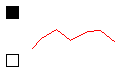
Arrow class displays a vector.
The position of the origin (Origin[:] variable) and horizontal and vertical components of the vector (Length[:] variable) can be
linked to the model variables.
| Type | Name | Default | Description |
|---|---|---|---|
| Color | color[4] | {0,0,0,255} | string color |
| Integer | intOrigin | 0 | = 0 if the center change in time and 0 otherwise |
| Integer | intLength | 0 | = 0 if the center change in time and 0 otherwise |
| Real | stroke0 | 2 | Stroke used to draw the lines |
| Integer | intStroke | 0 | = 0 if the stroke change in time and 0 otherwise |
| Type | Name | Description |
|---|---|---|
| Parent | pLeft | Connector of drawable components |
| Child | cLeft | Connector of drawable components |
model Arrow "Draws an arrow"

            extends Drawable(numIntColor = 0, numInt = (intLength*2+intOrigin*2+intStroke));
  import Modelica.Utilities.*;

  parameter TypesDef.Color color = {0,0,0,255} "string color";

  parameter Integer intOrigin = 0
    "= 0 if the center change in time and 0 otherwise ";

  parameter Integer intLength = 0
    "= 0 if the center change in time and 0 otherwise ";
 parameter Real stroke0 = 2 "Stroke used to draw the lines";
 input Real stroke( min = 1, max = 10) "Stroke used to draw the lines";
 parameter Integer intStroke = 0
    " = 0 if the stroke change in time and 0 otherwise";
  input Real Origin[2] "position of the arrow origin";
  input Real Length[2] "horizontal and vertical components";

protected
 Integer j;

initial algorithm

 num :=Functions.processingFile(fComponent);
  Functions.arrow(fileName, "node"+String(pLeft.nodeReference), "node"+String(num), String(num), Origin, Length, color, intOrigin, intLength, stroke, intStroke);

equation
 colors[1] = -1;
algorithm
  vert[numInt+1] :=-1;
  j :=0;
 if (intOrigin>0 and intLength>0) then
   for i in 1:2 loop
     vert[i] := Origin[i];
     vert[i+2] := Length[i];
     j :=j + 1;
   end for;
 if (intStroke >0) then
   vert[j+1] :=stroke;
 end if;
 end if;
 if (intOrigin>0 and intLength==0) then
  for i in 1:2 loop
     vert[i] := Origin[i];
     j :=j + 1;
   end for;
 if (intStroke >0) then
   vert[j+1] :=stroke;

 end if;
 end if;

 if (intOrigin==0 and intLength>0) then
  for i in 1:2 loop
     vert[i] := Length[i];
     j :=j + 1;
   end for;
 if (intStroke >0) then
   vert[j+1] :=stroke;

 end if;
 end if;

equation
 if (intStroke == 0) then
                          stroke = stroke0;
                                            end if;
end Arrow;
 VirtualLabBuilder.src.ViewElements.Drawables.Trail
This class inherits from the Drawable class.
Creates a drawing element that displays a sequence of points at given coordinates of the hosting container.
The point coordinates (point[:] variable) can be linked to the model variables.
| Type | Name | Default | Description |
|---|---|---|---|
| Integer | maximumPoints | 100 | Maximum number of points to be drawn |
| Integer | nSkip | 100 | Number of points to skip before plotting one |
| Color | lineColor[4] | {0,0,0,255} | Line color |
| booleanValue | connected | "true" | Whether to connect next point with the previous |
| Type | Name | Description |
|---|---|---|
| Parent | pLeft | Connector of drawable components |
| Child | cLeft | Connector of drawable components |
model Trail "Draws a trail"

              extends Drawable(numIntColor = 0, numInt = 2);

  import Modelica.Utilities.*;
  parameter Integer maximumPoints = 100 "Maximum number of points to be drawn";
  parameter Integer nSkip = 100 "Number of points to skip before plotting one";
  parameter TypesDef.Color lineColor = {0,0,0,255} "Line color";
  parameter TypesDef.booleanValue connected = "true"
    "Whether to connect next point with the previous";
  input Real point[2] "Coordinates x and y of the new point";

initial algorithm

  num :=Functions.processingFile(fComponent);
  Functions.trail(fileName, "node"+String(pLeft.nodeReference), "node"+String(num), String(num),
  point, maximumPoints, nSkip, connected, lineColor);

algorithm
  vert[numInt+1] :=-1;
 for i in 1:2 loop
     vert[i] := point[i];
 end for;
equation
   colors[1] = -1;

end Trail;
 VirtualLabBuilder.src.ViewElements.Drawables.TrailSet
Draws a set of elements of the Trail class.
| Type | Name | Default | Description |
|---|---|---|---|
| Integer | N_trails | 2 | Number of trails |
| Integer | maximumPoints | 100 | Maximum number of points to be drawn |
| Integer | nSkip | 1 | Number of points to skip before plotting one |
| Color | lineColor[4] | {0,0,0,255} | Line color |
| booleanValue | connected | "true" | Whether to connect next point with the previous |
| Type | Name | Description |
|---|---|---|
| Parent | parent | Connector of the drawable elements |
| Child | child | Connector of the drawable elements |
model TrailSet "Draws a set of trails"
  parameter Integer N_trails = 2 "Number of trails";
  parameter Integer maximumPoints = 100 "Maximum number of points to be drawn";
  parameter Integer nSkip = 1 "Number of points to skip before plotting one";
  parameter TypesDef.Color lineColor = {0,0,0,255} "Line color";
  parameter TypesDef.booleanValue connected = "true"
    "Whether to connect next point with the previous";
  input Real point[N_trails, 2] "position of the point (x1, y1)";

 Trail trails[N_trails](each maximumPoints = maximumPoints, each nSkip = nSkip, each
      lineColor =                                                                      lineColor, each
      connected =                                                                                                  connected);
  VirtualLabBuilder.src.Interfaces.Parent parent
    "Connector of the drawable elements";
  VirtualLabBuilder.src.Interfaces.Child child
    "Connector of the drawable elements";
equation
    connect(trails[1].pLeft,parent);
    connect(trails[N_trails].cLeft,child);
 for i in 1:N_trails-1 loop
    connect(trails[i].cLeft,trails[i+1].pLeft);
 end for;
 for i in 1:N_trails loop
    trails[i].point = point[i,1:2];
 end for;
end TrailSet;
 VirtualLabBuilder.src.ViewElements.Drawables.PolygonSet
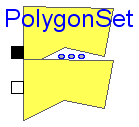
Draws a set of elements of the Polygon class.
| Type | Name | Default | Description |
|---|---|---|---|
| booleanValue | filled | "true" | True if the poligon is filled and false otherwise |
| Color | lineColorp[4] | {0,0,0,255} | The color used for the lines of the component |
| Color | fillColorp[4] | {0,0,255,255} | The color used to fill the component |
| Integer | intLineColor | 0 | 1 if the line color change in time and 0 otherwise |
| Integer | intFillColor | 0 | 1 if the filling color change in time and 0 otherwise |
| Integer | N | 2 | Number of polygons |
| Integer | nPoints | 1 | Number of vertices |
| booleanValue | closed | "true" | True if the poligon is closed and false otherwise |
| Integer | intVertexesX[:] | zeros(nPoints) | intVertexesX[i] = 1 if coordinate x of vertex i changes in time |
| Integer | intVertexesY[:] | zeros(nPoints) | intVertexesY[i] = 1 if coordinate y of vertex i changes in time |
| Real | stroke | 1 | Stroke used to draw the lines |
| Integer | gradient | 0 | 1 if there is a gradient in the filling color |
| Real | p1[2] | zeros(2) | Position where the color gradient starts |
| Color | color1[4] | {192,192,192,255} | Color at point p1 |
| Real | p2[2] | {0,10} | Position where the color gradient finishes |
| Color | color2[4] | {64,64,64,255} | Color at point p2 |
| booleanValue | cyclic | "true" | True if the color gradient is cyclic |
| Type | Name | Description |
|---|---|---|
| Parent | parent | Connector of the drawable elements |
| Child | child | Connector of the drawable elements |
model PolygonSet "Draws a set of polygons"
    parameter TypesDef.booleanValue filled = "true"
    "True if the poligon is filled and false otherwise";
  parameter TypesDef.Color lineColorp = {0,0,0,255}
    "The color used for the lines of the component";
  parameter TypesDef.Color fillColorp = {0,0,255,255}
    "The color used to fill the component";

  parameter Integer intLineColor = 0
    "1 if the line color change in time and 0 otherwise";
  parameter Integer intFillColor = 0
    "1 if the filling color change in time and 0 otherwise";
  parameter Integer N = 2 "Number of polygons";
  parameter Integer nPoints = 1 "Number of vertices";
  parameter TypesDef.booleanValue closed = "true"
    "True if the poligon is closed and false otherwise";
  parameter Integer intVertexesX[:] = zeros(nPoints)
    "intVertexesX[i] = 1 if coordinate x of vertex i changes in time";
  parameter Integer intVertexesY[:] = zeros(nPoints)
    "intVertexesY[i] = 1 if coordinate y of vertex i changes in time";
  parameter Real stroke = 1 "Stroke used to draw the lines";

  input Real x[N, nPoints] "X coordinates of the polygon vertices";
  input Real y[N, nPoints] "y coordinates of the polygon vertices";
  parameter Integer gradient = 0
    "1 if there is a gradient in the filling color";
  parameter Real p1[2] = zeros(2) "Position where  the color gradient starts";
  parameter TypesDef.Color color1 = {192, 192, 192, 255} "Color at point p1";
  parameter Real p2[2] = {0, 10} "Position where the color gradient finishes";
  parameter TypesDef.Color color2 = {64, 64, 64, 255} "Color at point p2";
  parameter TypesDef.booleanValue cyclic= "true"
    "True if the color gradient is cyclic";

  input Real lineColor[N,4];
  input Real fillColor[N,4];
 Polygon polygons[N](each filled = filled,
   each intLineColor = intLineColor, each intFillColor = intFillColor, each
      nPoints =                                                                       nPoints, each
      closed =                                                                                               closed,
   each intVertexesX = intVertexesX,
   each intVertexesY = intVertexesY, each stroke = stroke, each gradient = gradient, each p1 = p1, each
      color1 =                                                                                                  color1,
   each p2 = p2, each color2 = color2, each cyclic = cyclic, each lineColorp = lineColorp, each
      fillColorp =                                                                                           fillColorp);
  VirtualLabBuilder.src.Interfaces.Parent parent
    "Connector of the drawable elements";
  VirtualLabBuilder.src.Interfaces.Child child
    "Connector of the drawable elements";
equation
    connect(polygons[1].pLeft,parent);
    connect(polygons[N].cLeft,child);
 for i in 1:N-1 loop
    connect(polygons[i].cLeft, polygons[i+1].pLeft);
 end for;

 for i in 1:N loop
    polygons[i].x = x[i,1:nPoints];
    polygons[i].y = y[i,1:nPoints];
    if (intLineColor> 0) then
     polygons[i].lineColor = lineColor[i,:];
    else
     lineColor[i,:] = lineColorp;
    end if;
    if (intFillColor > 0) then
     polygons[i].fillColor = fillColor[i,:];
    else
     fillColor[i,:] = fillColorp;
    end if;

 end for;
end PolygonSet;