 |
|
|||||||||||||||||
Fig.
7.9: View of the virtual-lab. |

Fig.
7.42: Schematic description of the system.

Fig.
7.43: Introduction of the virtual-lab.


Fig.
7.44: View of the virtual-lab.
7.10
CONTROL OF THE BALL & BEAM SYSTEM |
| << previous | next
>> |
|
||||||||||||||||||||||
| System description | ||||||||||||||||||||||
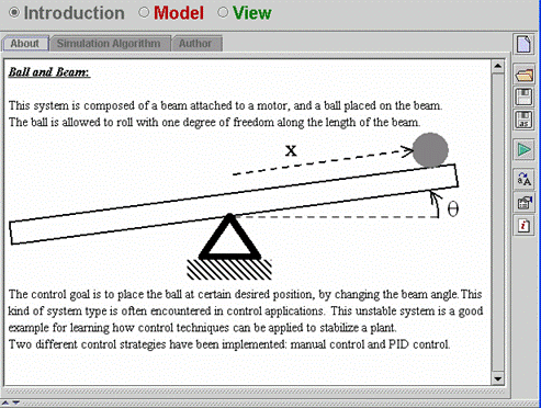
| This system is composed of a beam attached to a motor, and a ball placed on the beam. The ball is allowed to roll with one degree of freedom along the length of the beam. A diagram of this system is shown in Fig. 7.42. | ||||||||||||||||||||||
 |
||||||||||||||||||||||
Fig.
7.42: Schematic description of the system. |
||||||||||||||||||||||
| The
control goal is to place the ball at certain desired position ( |
||||||||||||||||||||||
| Introduction | ||||||||||||||||||||||
| The virtual-lab introduction is shown in Fig. 7.43. | ||||||||||||||||||||||
 |
||||||||||||||||||||||
Fig.
7.43: Introduction of the virtual-lab. |
||||||||||||||||||||||
| Model | ||||||||||||||||||||||
| The model that describes the ball movement has the following equations: | ||||||||||||||||||||||
 |
||||||||||||||||||||||
| The discrete PID controller has two degree of freedom and anti-windup. The algorithm of this controller can be found in “Computer Controlled Systems. Theory and Design, Prentice Hall. Astrom, K. J. and Wittenmark, B. (1997)”. | ||||||||||||||||||||||
| View | ||||||||||||||||||||||
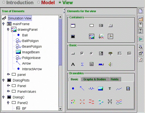
| The tree of elements is shown in Fig 7.44. Open the virtual-lab and look at the properties of the tree elements. | ||||||||||||||||||||||
 |
||||||||||||||||||||||
Fig.
7.44: View of the virtual-lab. |
||||||||||||||||||||||
| << previous | next
>> |